#019 Resonance in E-Miata
last updated: 6/4/23
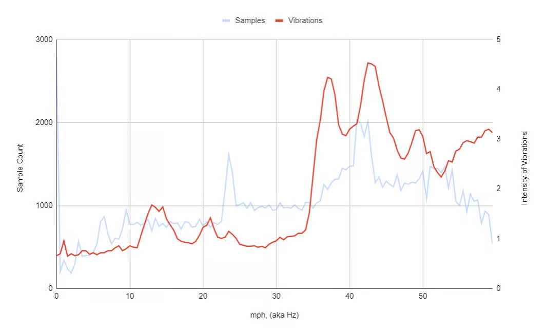
After I upgraded the drivetrain in my electric Miata, I noticed a vibration when the car approached 35-40 mph. The vibration was not present before the upgrade, so I knew something about the upgrade was at fault.
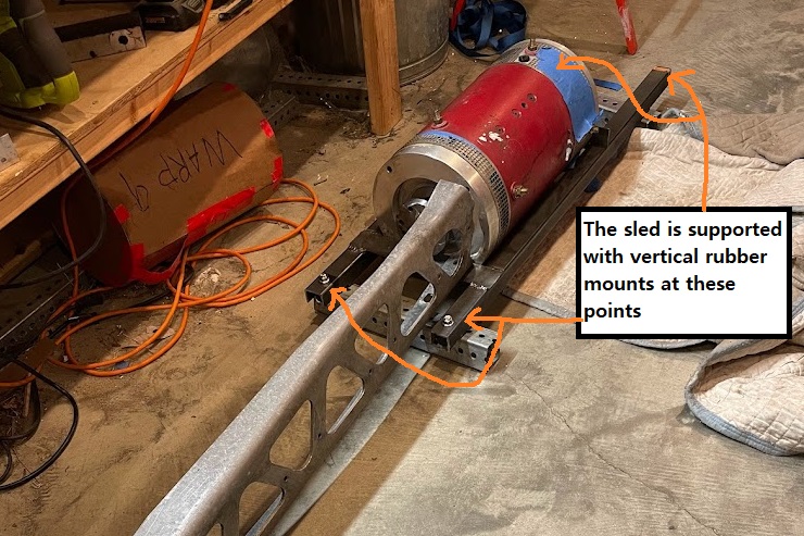
For reference - the upgrade consists of a 150lb DC motor rigidly mounted to a subframe dubbed "the sled". The sled in turn is mounted via rubber mounts. (archive here)
I proposed at the time that a combination of resonance of the sled car system and an off balance adapter was at fault. To confirm this, I used the Arduino Nano mounted to the front of the car frame with attached accelerometer (an MPU6050, used for a g force sensor). The Arduino Nano in the front of the car also is responsible for recording the speed of the motor and therefore also knows the speed of the car.
My first idea was to create a frequency response diagram for the the intensity of the vibrations. I sampled the magnitude of the acceleration and the current speed with the sled in the car, with the driveshaft disconnected. The code summed the magnitudes of the acceleration and stored it based on the measured speed. I modulated the throttle and collected about 500 datapoints for each speed.
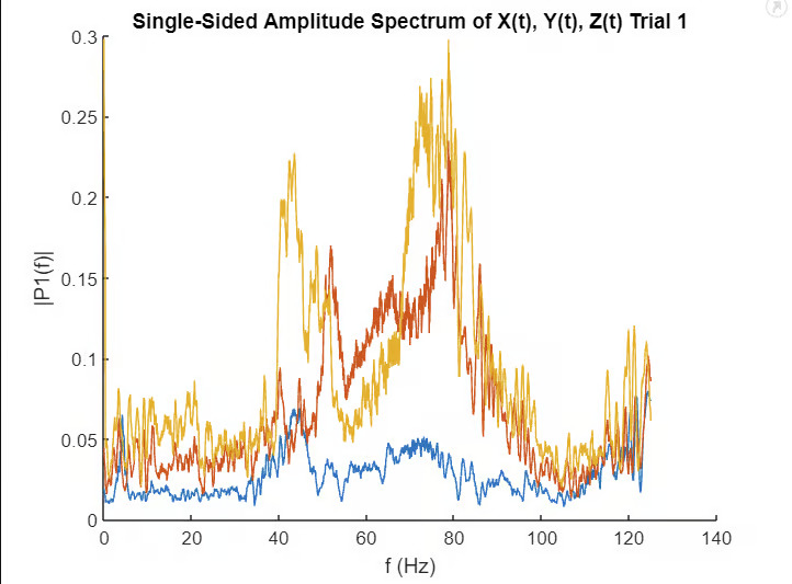
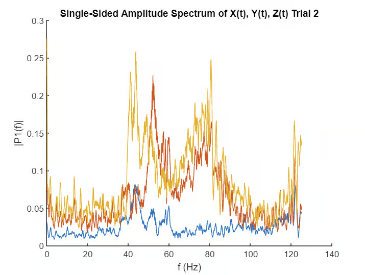
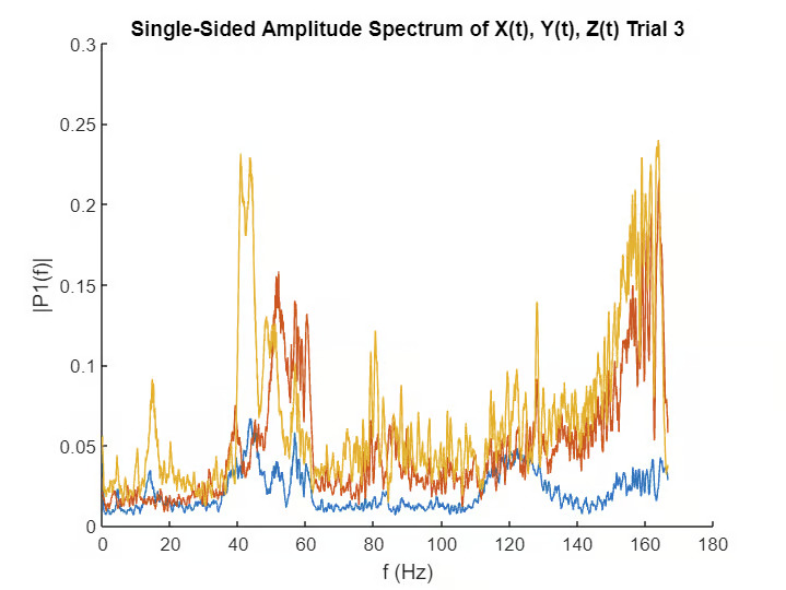
This worked, but what would solidify my diagnosis would be to see harmonics of this resonance. For this analysis, the best method would be to take a discrete FFT. I sampled all three axis of the accelerometer for about 10 seconds through a range of speeds. The FFT charts were smoothed with a moving average with a window of 10.
Turns out the sled was contacting the frame. I lifted the rubber mounts with washers on either side and that fixed it.
