#010 E-Bike
Where to even start? The bike project began when I started working at a nearby summer camp and biked to work every day. I think the distance was less than a mile, but I knew there had to be a better way than to exert all of that energy. My design consists of a 2.8 kW RC Brushless motor (more like 1kW in reality), many 3D printed pulleys with a couple of timing belts.
Rear Pulley
I first attacked the rear pulley. My bike had very limited space for a pulley to be mounted. I knew the
teeth needed to be 3D-Printed, and that the center must be supported with metal. I
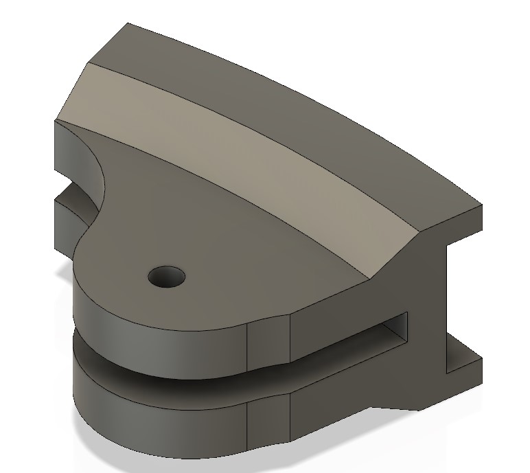
originally planned to have two halves of the disk and slide them on (see right or above: this was a test
print of
a section of the original design). The prints ended up warping by a small amount, and the teeth did not
line up where
the two ends met.
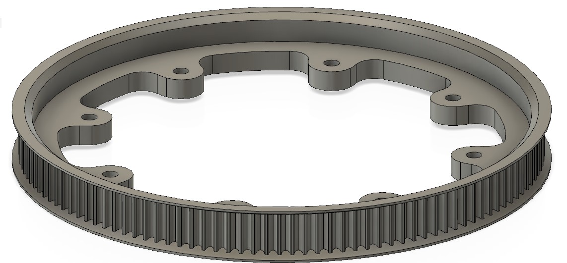
I solved this problem but printing the entire pulley in one print. I don't know if warping is still a
problem, but the teeth line up now. The aluminum disk lays down in the center of the 3D Printed section
and is bolted in eight places around the wheel. I mounted the pulley to the wheel with copious amounts
of zip-ties. I originally used smaller ones, but those actually broke. I never thought I would say this,
but the zip ties broke. (Editors note: many more things were to break...)
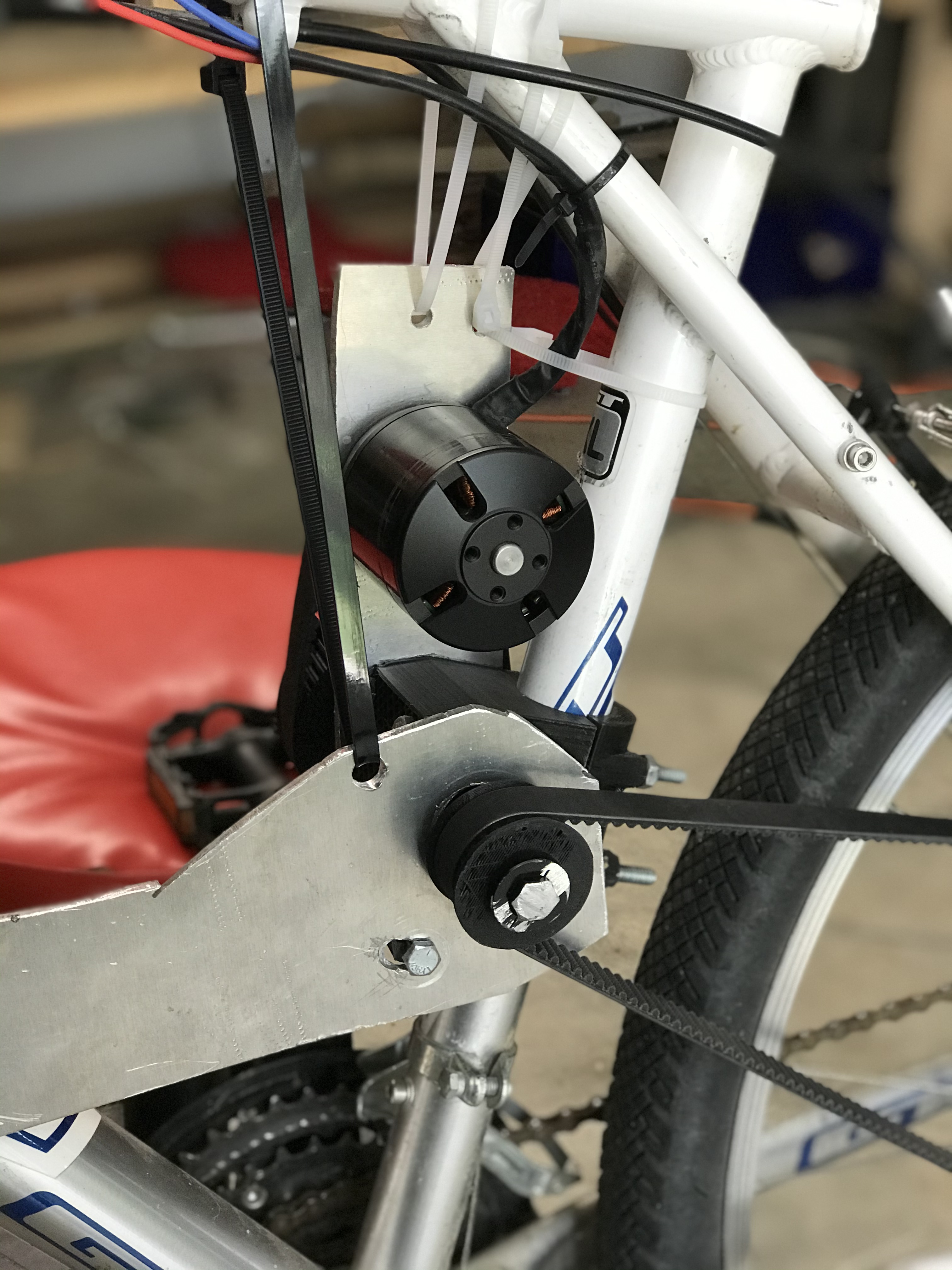
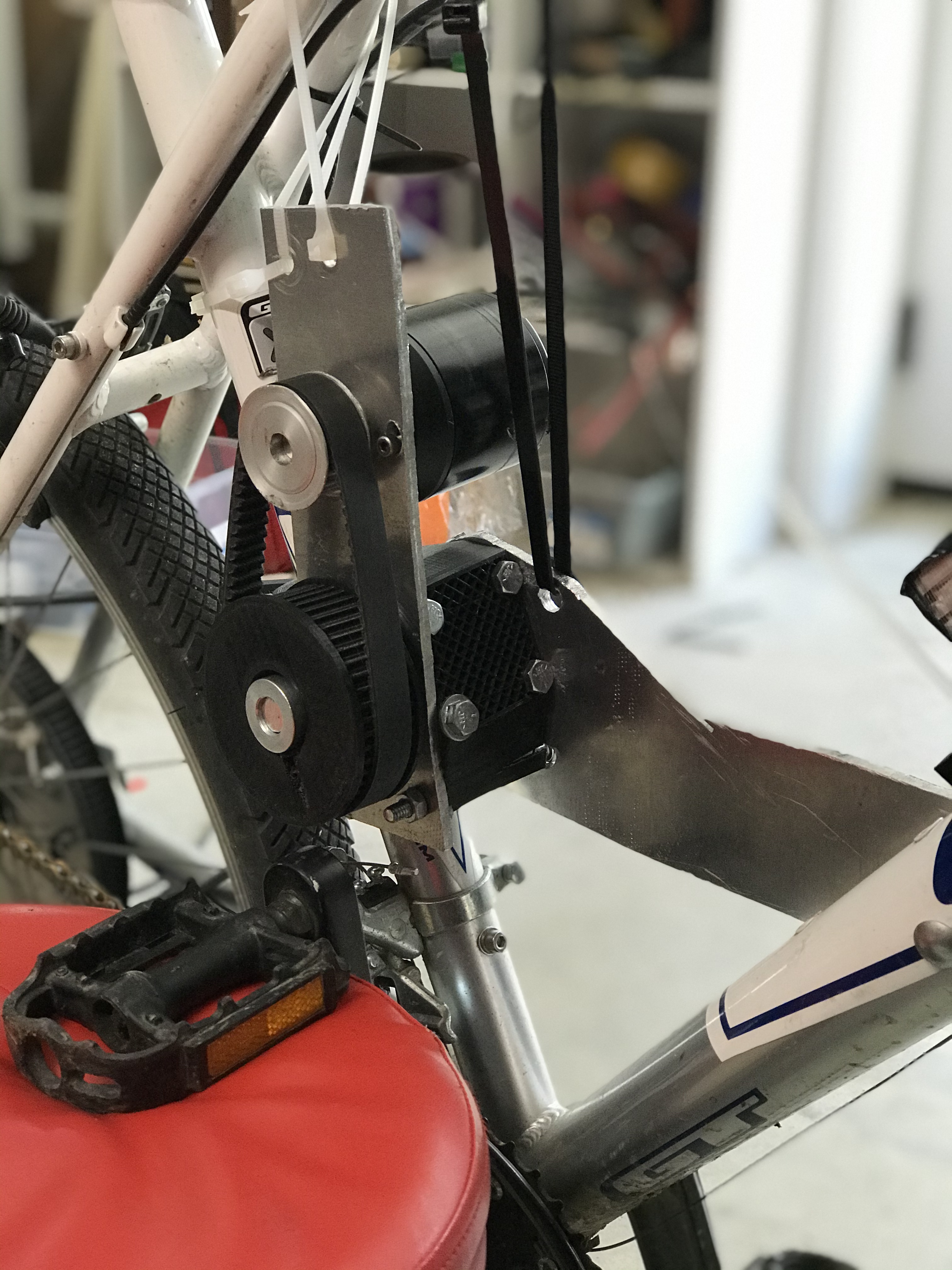
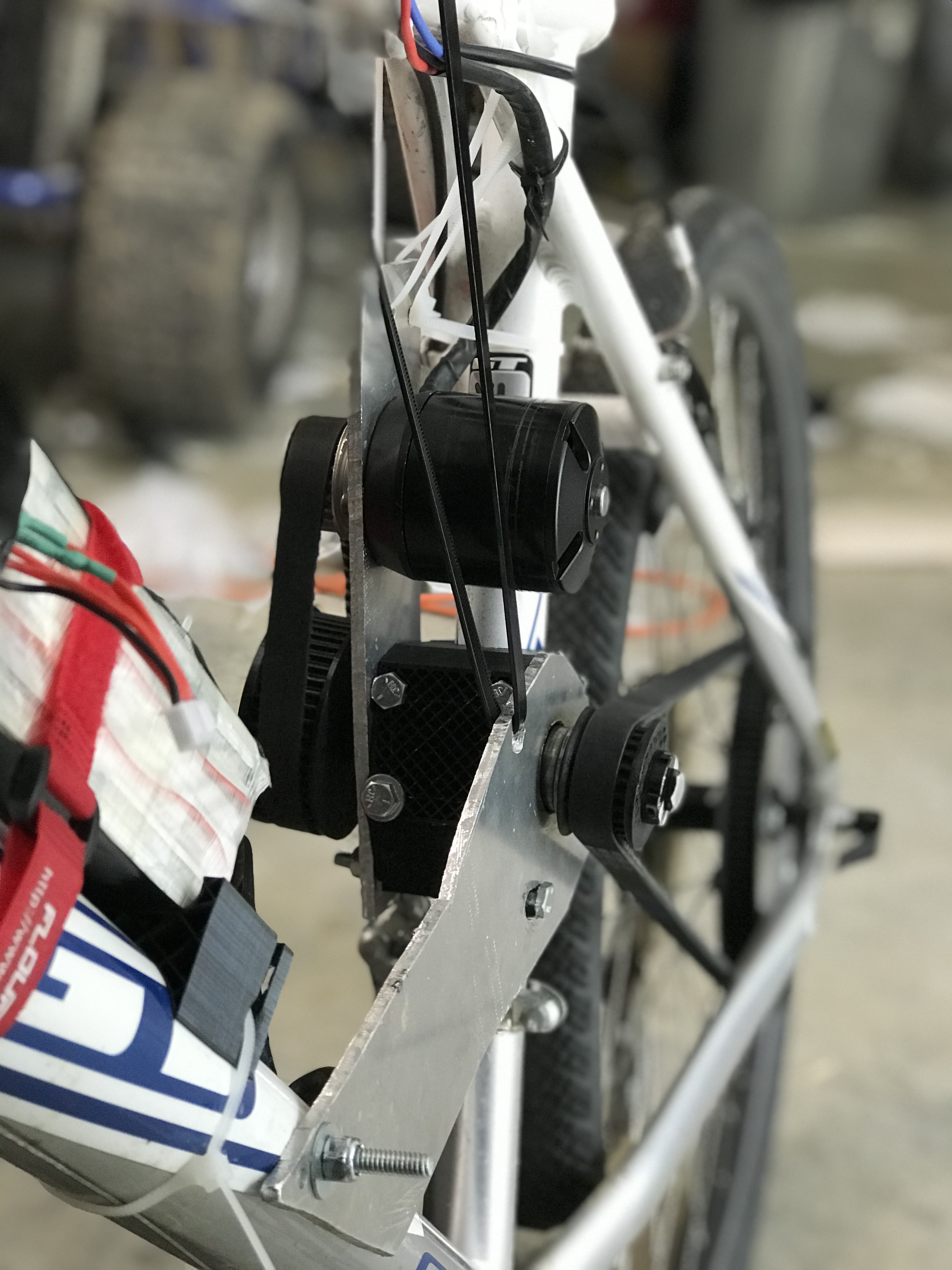
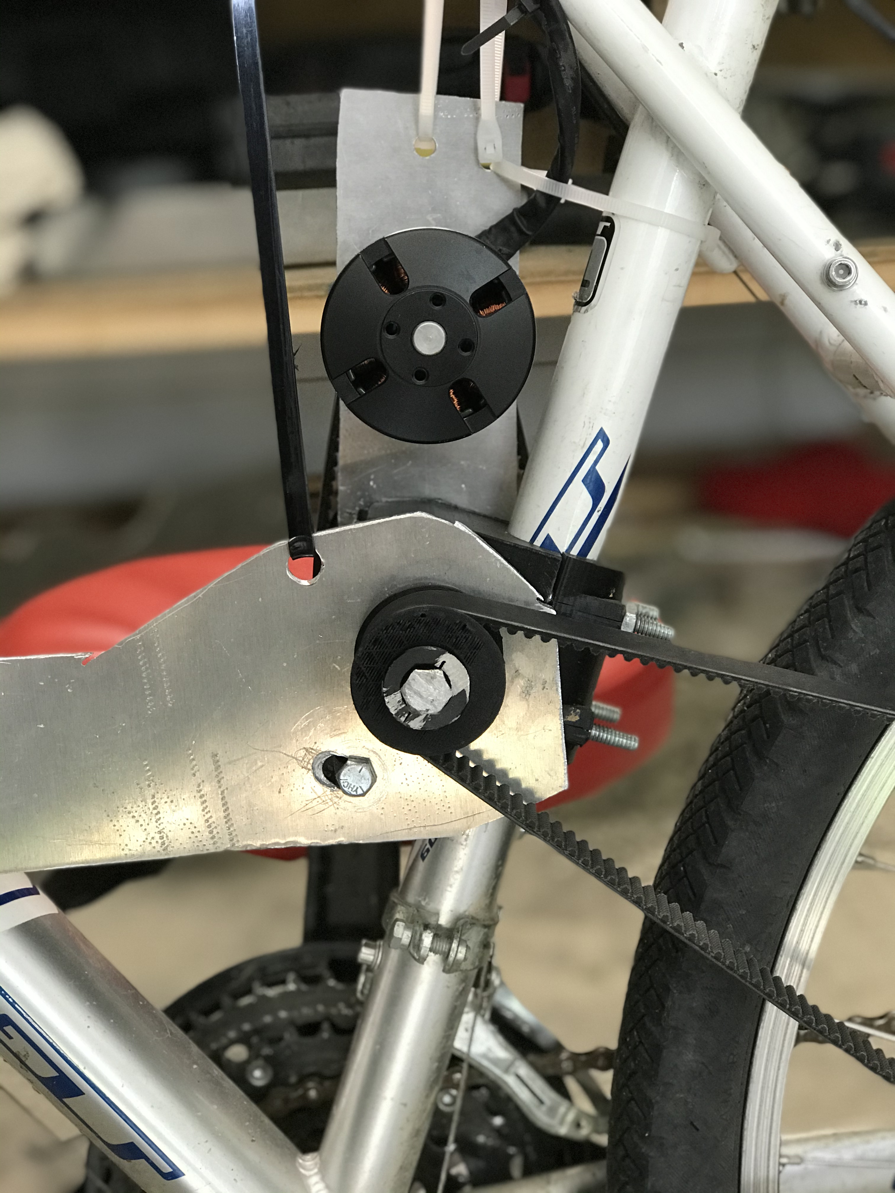
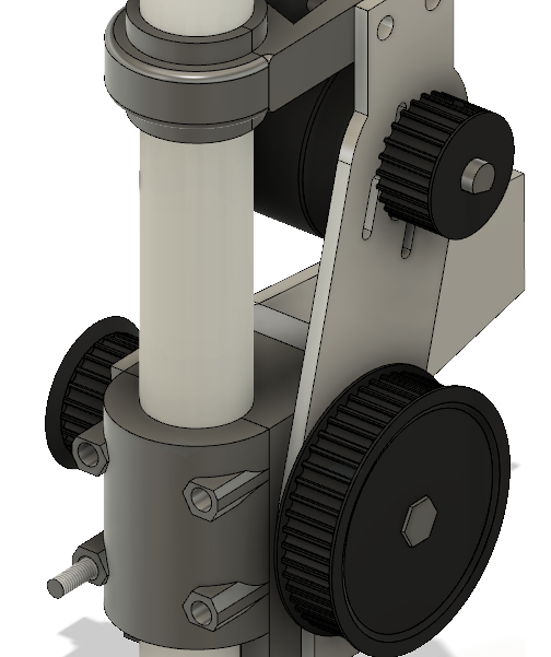
Next: the design on the front. I knew based on the size of my rear pulley I needed at least one more step down on the motor. The pulley on the left is connected to a belt that goes back to the wheel. The motor is geared down 2:1 to the main axle. I used half-inch hex for the center shaft and printed all pulleys. Under high force and heat coming through the motor shaft, the upper pulley would melt, so I ended up purchasing a metal pulley for the pulley connected to the motor. I did think I would end up replacing the other pulleys on the hex shaft, but they turned out to be strong enough. I reinforced the center of the hex pulleys with 100% infill. Also, I ended up not adding the support at the top, as the vertical bracket was securely bolted to the bottom bracket.
Electronics
I used an Arduino Nano to convert the input from the twist grip to the motor PWM signal. I
also added some artificial current limiting to limit the force going through the system: A simple time-based
ramp up ensured I wouldn't push my parts too far. When I picked up the project again during Corona-cation, I
added a Hall Effect sensor and a magnet on the wheel giving myself a multitude of new things to fiddle with. A
2.5 inch
monochrome screen also helped: I coded myself a speedometer, trip odometer, total odometer and best of all,
cruise control. All of which printed on the screen.
I used a 6s Lipo Battery to power the bike. I had one cell die on me, so I opened up the battery and shorted it
with a jumper wire. Now I
operate as a 5s, but another 2s battery is coming soon with the same Mah and C rating to push us up to 7s, (26
volts). (See update on the V2 page)
The Final Product
I spent a few month chasing down mystery (ok, not so mysterious) forces that plagued the weak 3D Printing mindset I previously held and strategically placing zip-ties in order to balance them out.